
Important: the length of the wires should not exceed 10 centimeters, the wires should not be intertwined.
Pinout of the connectors: A1...A25 and B1...B25 correspond to the Communication cart connector (signed on the board), the cells indicate the name of the signal and the pin number on the modem connector with which the communication cart contact should be connected.
Contacts in the red fields do not need to be connected. It is enough to connect power supply (+3.3) and ground (GND) to the modem board with one wire.

I will describe the assembly process using the HKT-3030 modem as an example (I assembled two of them, for myself and for a friend).
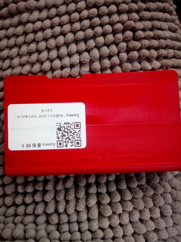
Preparing a communication cart:
We disassemble, heat the plastic connector with a hair dryer (150°C) during the heating process, gently move it and remove it from the contacts.
We heat the board on both sides with a hairdryer and desolder the metal contacts.
Remove solder from holes.

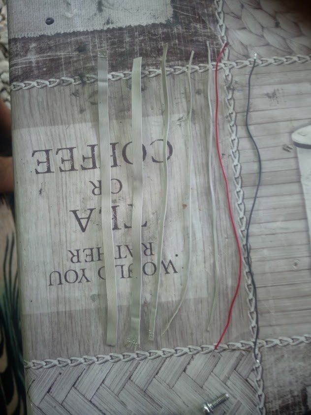
We cut an 80 pin IDE cable, we need 15 centimeters long segments, we divide into strips 2 * 8 cores, 1 * 4 cores, 2 * 2 cores and two wires for power supply (preferably red and black so as not to get confused, I used a USB cable)
We disassemble the modem, put aside the internal metal screen, we will no longer need it.
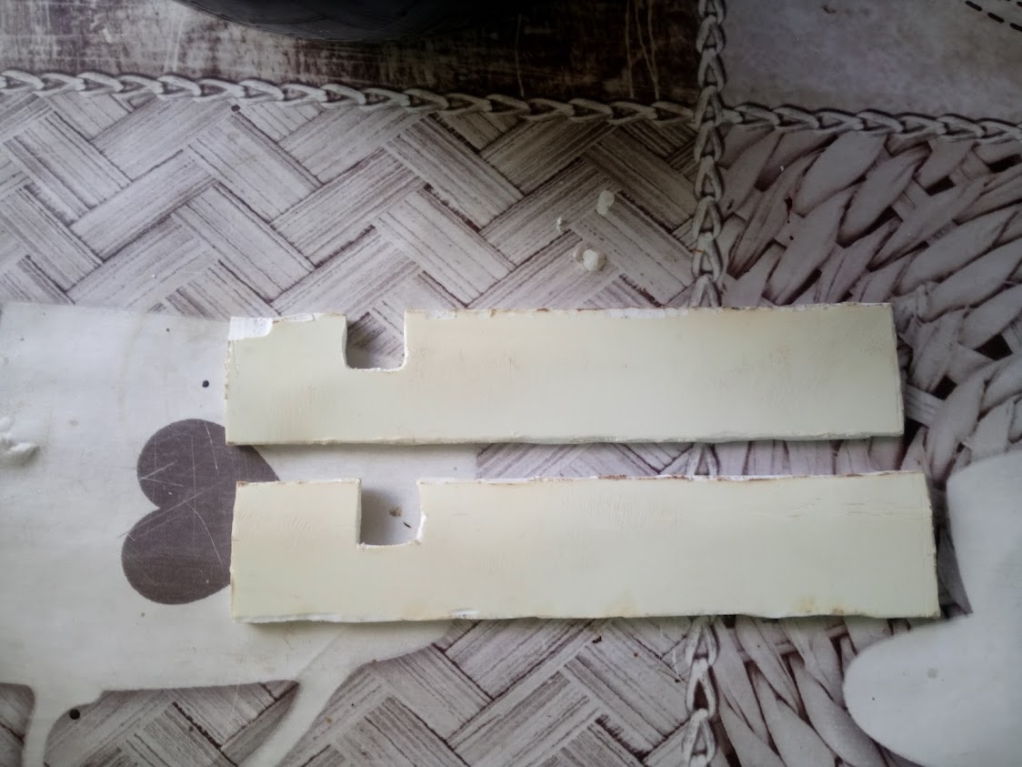
Carefully make two cuts under the wires in the upper part of the modem board (seen in the photo).
We take a piece of IDE cable (8 cores), separate one core and solder it to pin 26.

We put the wire in the cut and bend it to the other side of the board.

Be sure to cut off the extra wire (about 3 centimeters).
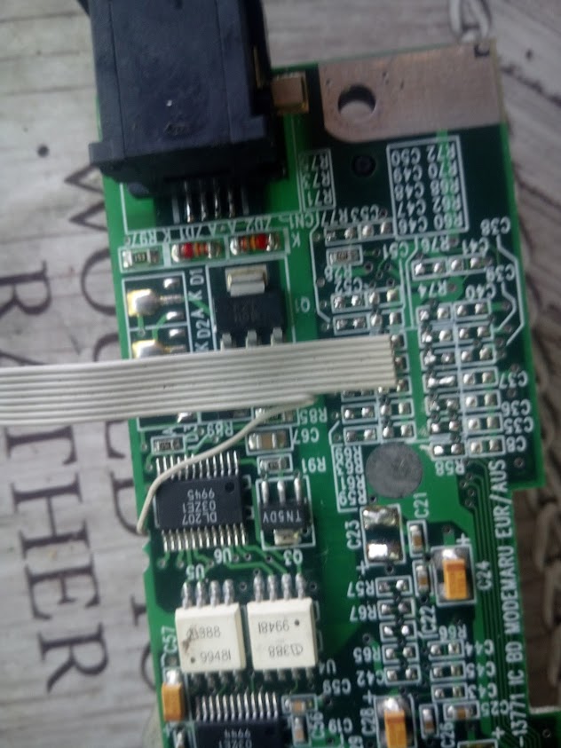
We divide the ends of the remaining seven cores, clean, tinker, bend with tweezers to the resistor pads and solder.
Important: you can solder only to the top three contacts, the bottom row is the ground, you can not solder to it.

We take the second segment of the IDE cable (8 cores), separate one core and solder it to pin 25.

Similarly, with the first eight-core segment, we bend to the other side of the board, cut off the excess, divide the ends of the remaining seven cores, clean, tin, bend with tweezers to the resistor pads and solder.

We take a piece of IDE cable (2 cores) and solder it to contacts 13 and 21, bend it to the other side of the board.
We take a piece of IDE cable (4 cores), separate one core and solder it to pin 22.

We put the wire into the cut and bend it to the other side of the board and solder it to the pads R66, R67, R57.
We take the last piece of IDE cable (2 cores) and solder it to R76, R77.

We solder the power wires to C23 (I did not take a photo, I marked it with red and black squares).

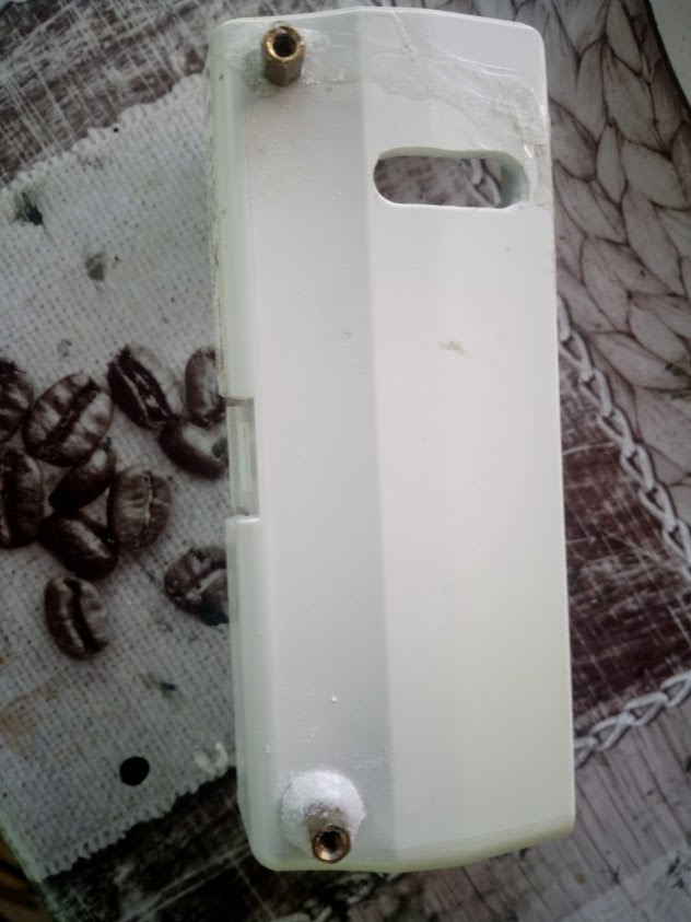
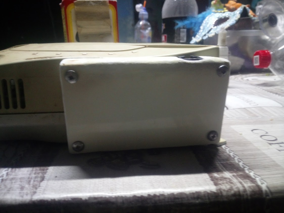
We make a cut in the modem housing.
We attach the communication cart to the case leaving a gap on all sides and mark the places for the lower fasteners.
We drill holes for brass racks and screw them in.
We push all the wires into the hole so that the wire from the 25th leg is on the bottom left, and from the 26th leg is on the bottom right.
We insert the modem into the housing and cut off the extra wires.

We pull out the modem board from the seats and shift it as much as possible to the slots in the housing, so that the wires stick out of the housing more and it was convenient to solder them.
We divide all the wires into a length of one centimeter, clean and tin.
We bend the wires of each eight-wire segment into different ones through one, the upper left/right kA4/B4, the next A5/B5, etc.
We insert the left eight-core into the holes on the BBA and solder, we repeat the same with the right one.
We solder the remaining wires and screw the board into place.

If you are not sure about soldering, then you can (and even need to) ring all the contacts.
All the modem can be twisted into place, but first glue two wires in the cuts of the modem board with a piece of duct tape, this will not allow them to jump out and close to the metalic screen.
I will not describe the creation of the case, it is done individually, someone will do it on a 3D printer, someone will glue it from plastic, and someone will leave it as it is.
Personally, I glued with cyanocrylate glue made of plastic 2.5 mm thick and this is my first experience of creating a case, I'll just show what I got.


 '}">show spoiler»