Below are some pictures and instructions to build a Dreamcast which keep both the GD-ROM drive and include a 500 Gb SSD disk, with everything fitting in the original plastic shell !
The general approach to reach this funny combo is the following :
- the GD-IDE mod, which in combination with the Dreamboot GD-IDE bios allow selecting between GD-ROM or SSD boot via a small switch
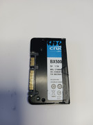
- a 500Gb Crucial SSD hard drive, in which the SSD circuit board is actually very small compared to the 2,5'' hard drive form factor and fits in the console
- a modern PSU (power supply unit): that is smaller than the original PSU board, and on top of avoiding overheating issues, is small enough to let space for the SSD hard drive board and Sata to IDE adaptor
- VA0 or VA1 motherboards, not compatible with VA2 : because the GD-IDE mod is not compatible with V2
- this is a hard mod : bios replacement, board cuts with a dremel... you need a minimum of soldering and tooling skills !
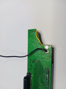
- at the end, there will still be a small switch taped on the side of the shell. I did not, so far, found a way to hide it in one of the shells holes.
- a soldering station, with a heat gun
- a dremel, or any other precision tool allowing to cut a corner of circuit board
- a few thin wires that will be soldered
I bought several parts, in particular the GD-IDE and Dreamboot bios chip from boutique-dragoncity.myshopify.com.
This is a French retailer, most instructions are in French but can be easily translated with current browsers, and equivalent mods may be available from other retailers.
None of the boards that are sold by dragoncity are "compulsory" for this mod, but really, his DIY board facilitates so much the IDE cable soldering to the GD-ROM board... everything is just "cleaner".
I am not affiliated to this shop, but never got disappointed.
That being said, here is the parts list:
- GD-IDE parts :
- custom bios, with Dreamboot flashed (https://github.com/Cpasjuste/dreamboot)
- Dreamcast - PCB GD-IDE « V3 » link)
- 80 pins IDE cable (included in the dragoncity PCB GD-IDE « V3 » pack)
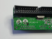
- IDE/SATA adaptor, one of the models "M03C" or "JP103-5" or "RXD-629A7-7": other models may work, but those are recommended, and I'm sure they will fit link
- l Crucial BX500 SATA SSD 480Go, SSD 2.5" (model CT480BX500SSD1). This is 480gb to extend your Dreamcast ! The 1Tb model might be OK if the board inside the SSD shell is actually small enough (as show below in the pictures). I never tried, but if you do, please report your finds here.
- PSU parts :
- I bought the dragoncity model, but any other PSU should work as soon as it is not a larger size and deliver enough power to everything link
- >=5A power supply for the PSU, e.g. with enough juice to power everything : I bought this one link
3) TUTORIALS TO READ BEFOREHAND, e.g building the GD-ROM+IDE cable combo :
The current tutorial can be seen as an iteration of all the excellent tutorials available on dragoncity's website. I basically followed them years ago to install the Dreamboot + Retrodream setup. Booting as usual with the GD-ROM or from the IDE drive is done via a switch at console boot.
Please, read first the GD-IDE/Dreamboost explanations link, then the PSU replacement explanations. First, install these mods while keeping the console open. Verify that everything is functional, then continue to the tutorial below. From them, I explored how to fit everything in the console shell.
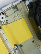
Just to make it clear, you should start from a GD-ROM drive connected to the IDE cable, here is a picture.
4) ACTUAL TUTORIAL :
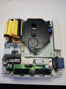
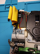
Let's go straight to the point. Here is the aimed result.
On the bottom left of the GD drive is the modern PSU, on the top left some IDE cable is overlapping the SSD drive (black rectangle) and the IDE to SATA adaptor (vertical board). Everything fits !
Now a step-by-step tutorial with images.
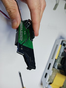
4.1. Open and cut the SSD
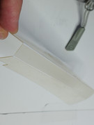
- open the outer metallic shell, just bend gently the sides with a thin screwdriver.
- you will see the board, just mark the shell where the board ends and cut it with a dremel or metal saw
- you should obtain this :
- then close the shell and seal it with same tape.
If not already done (dragoncity tutorials), install retrodream) and all the GDIs that you need on the SSD.
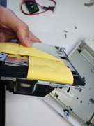
4.2. Carefully put back the GD-ROM drive
- gently fold the IDE cable so that is make an 90° angle and pops out on the PSU side from below the GD-ROM drive.
- put back the drive.
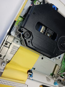
- DO NOT fully tighten the driver screw that is on the back of the console, that would crush the IDE cable, just let half a millimetre so that the cable has some room.
- take the plastic piece which separated the PSU from the RF shield which cover the motherboard, and bend its side so that it fits on top of the IDE cable
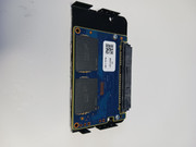
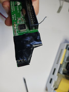
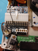
4.3. Hardest part : trim the side of the IDE to SATA adaptor
!!! This part might be skipped if the form factor of your PSU is small enough !!!
Mine, bought from dragoncity, was not.
But it is stable and powerfull, it powers the GD-ROM, SSD, IDE/SATA, mainboard and CPU 20% overcloack mod like a charm.
Some says the small factor PSUs may be less powerfull, be aware of this :
https://www.retrorgb.com/dreamcast-repl ... lysed.html
- here the goal is to cut a corner of the adaptor, so that there is enough room for the modern PSU.
- doing this involves 4 steps :
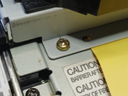
- unsolder the 2 big capacitors from their original side to the other side of the board (make sure capacitor positive and negative are correct)
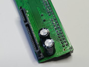
- unsolder the white power connector, then trim the board so that only the 2 pins near the IDE black connector are left. Do this with a dremel or any good tool allowing to precisely cut a board. This involves cutting one of the copper tracks which spans from the removed power connector the left pins of the leftmost transistor (just look the picture). We do not need any more the 12V of the IDE (this is useful only for non SSD hard-drives, to power the spinning motor).
- reconnect the cut track (the GROUND) to the transistor with a piece of wire
- solder a wire (~15 cm) to the 5V track of the now removed IDE power connector, this will be connected later to the 5V pin near the PSU later. This is the innermost pin, near the IDE connector.
That's it, now just tape all the trimmed area. We want to protect it because the copper of the cut board is somewhat exposed and the PSU will seat just near it, we want to avoid shortcuts !!
4.4. Tetris part : fit everything
- connect the SSD drive to the SATA/IDE adaptor, make it seat on the top of the plastic protective sheet, on the back of the console.
- connect the IDE cable to the adaptor
- if you use a 3 connector IDE cable, you can cut the part of the cable that is left, but the full cable will actually fit.
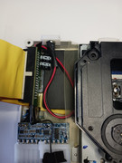
- put in place the PSU, its top will cover the corner of the trimmed adaptor
- do not forget to connect the 5V cable coming from the adaptor, I decided to not solder it andI just pinched it between the mother 5V pin and the PSU connector. this allow me to rapidly mount/unmount the setup if I want to update the files on the hard drive.
- close your shell, everything fits !
5. Test and confirm functionality
- in my case, everything was smooth and worked immediately. If you have issues, keep calm and verify all your connections.
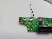
- the small blue wire that you saw on some pictures are connected to the custom BIOS and go to a micro-switch that I taped discretly on the on the bottom side of the console